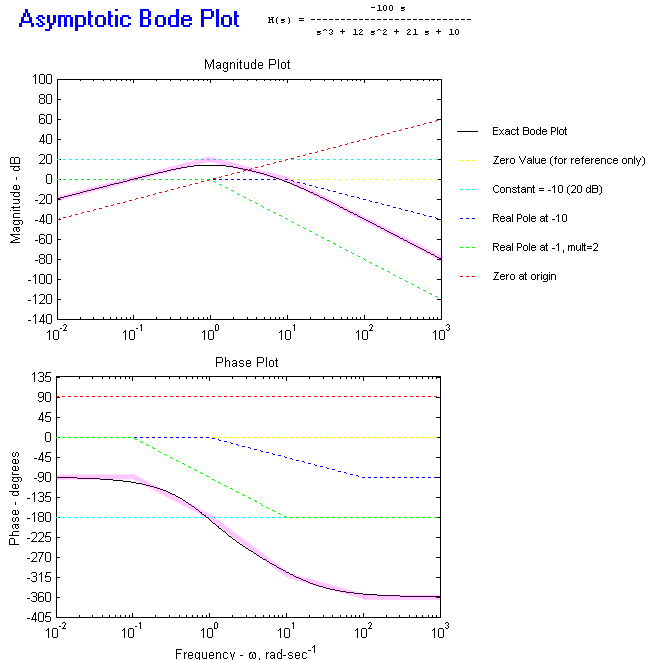

Now let's take a look at poles and zeroes. H of s represents a transfer function with two poles and two zeros. The s represents j omega, where omega is equal to 2 times pi times f. The frequencies at which each term in the numerator equals 0 are called zeros. The frequencies at which each term in the denominator equal 0 are called poles. Each pole and zero is factored to be s divided by omega plus 1. This is called the standard form, because it allows you to easily determine the pole and zero by inspection.įurthermore, notice that the DC gain is factored out of the transfer function. This makes it easy to determine the low-frequency gain.Ī plot of gain versus frequency for a pole is shown in the lower left. Notice that the gain is given as magnitude in dB. Note that the gain of a pole decreases or rolls off at a rate of negative 20 dB per decade in frequency. This makes sense because for higher frequencies, the denominator will become large, causing the magnitude to decrease. In the next slide, we will see more detail on this.Ī plot of gain versus frequency for a zero is shown in the lower right. Bode plotter multisim plus#Ī zero causes the gain to increase at a rate of plus 20 dB per decade in frequency. This also makes sense, because for higher frequencies, the numerator will become large, causing the magnitude to increase. This slide illustrates the equations for a pole and its associated response. Later, we will provide a real-world circuit example for a pole.

Looking at the equations, you can see that the first equation represents a pole as a complex number.Ĭomplex numbers have a real and imaginary part. For practical circuits, the complex function is converted to a magnitude and phase. The second equation shows the magnitude, and the third equation shows the phase. Taking 20 times the log base 10 of the magnitude gives the magnitude in dB. The graphs show the magnitude in dB as well as the phase in degrees. Notice that both the horizontal axis and vertical axis are logarithmic. Let's look at some key points on the Bode plot. First, the pole frequency is denoted by fp. For frequencies below fp, the gain is constant and is denoted by Gdc. In other words, the gain at DC, or zero frequency, would be Gdc.


 0 kommentar(er)
